
The first instrumented line: P-ONE-1
The next milestone on the route to P-ONE will be deploying the first instrumented mooring line, P-ONE-1, in 2025. P-ONE-1 aims to be the blueprint for the following detector lines and, as such, constitutes the first construction stage of P-ONE. Development of this first line started at the Technical University of Munich (TUM), Germany, in 2021.
The Design

P-ONE-1 is a 1000 m long mooring line with 20 evenly distributed optical and calibration modules. The integrated backbone cable, which carries all modules, will terminate in a mooring junction box (mJB), which acts as the interface to the infrastructure of Ocean Networks Canada's NEPTUNE network. P-ONE-1 will be held in position by an anchor and pulled taut by a subsea float.
The design emphasized developing the system as a cohesive whole, incorporating modular construction principles, and ensuring a scalable deployment approach. A novel backbone cable system, combining a load-bearing aramid braid with the hybrid electro-optical power and communication cable, circumvents the need for running wire or Dyneema ropes parallel to communication cables. This streamlines the mooring design and reduces the risk of entanglement during deployment.
The connection of the modules is performed by branching out the necessary number of copper and fiber strands via a titanium termination can. The remaining wires are fed through to the following instrument. A sophisticated multi-layered sealing system allows for maintaining a functioning system in case of cable or instrument failures. The titanium cylinders transfer the mechanical load of the structure and are an integral part of the detector line. The modules are hosted in 17" glass hemispheres which are adhesively connected to titanium flanges and screwed to the termination cylinders. The new backbone technique circumvents the need for subsea connectors and guarantees a free field-of-view for all photosensors.
The individual components of the backbone assembly, i.e., titanium cylinders and cable are stored on the so-called deployment frame. This mounting structure for the furled-up detector line allows access to individual instruments. Post-deployment, the frame serves as the anchor to P-ONE-1.
The P-ONE Optical Module (P-OM)
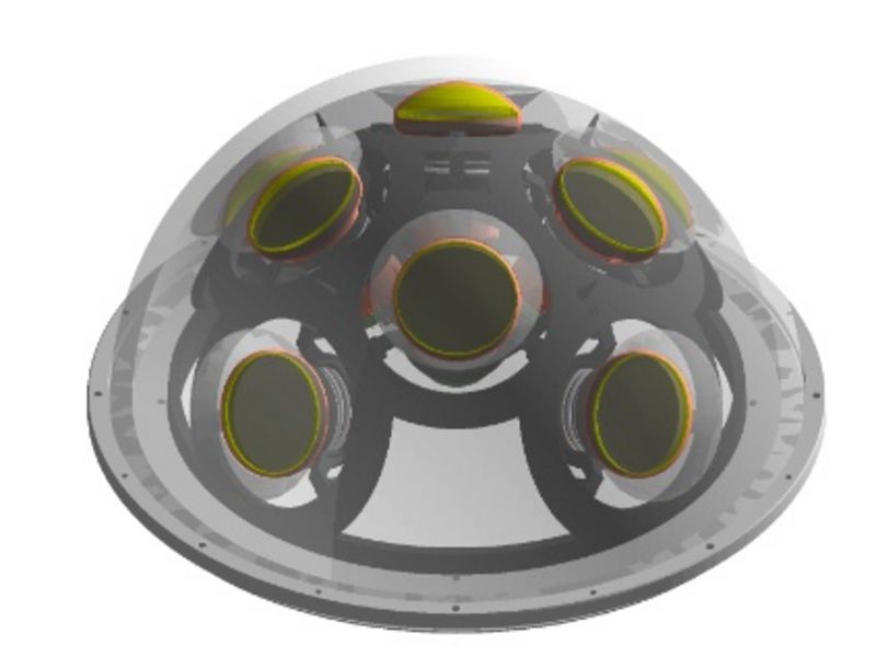
Each hemisphere of the optical module of P-ONE-1 houses eight photomultiplier tubes (PMTs) with a diameter of 3.1". To accommodate temperature gradients, hydrostatic compression, and shock and vibrational loads during deployment and transportation, the PMTs are mounted in a spring-loaded configuration. Optical coupling is provided by silicon-based optical gel pads, which utilize total internal reflection to increase the effective photocathode area. Additionally, photons with low incident angles missing the primary PMT can be collected by adjacent ones. The mounting scheme and the easily removable gel pads offer the possibility to safely swap PMTs during production and testing. The PMT is supplied with high-voltage by the micro base, which was initially developed for the IceCube Upgrade and offers a versatile low-power high-voltage supply for the PMTs. An automated calibration and test system for the characterization of PMTs and P-OMs has been developed at the Technical University of Munich. Here, a 405 nm laser serves as a light source, while rotational stages allow angular measurements. The setup will also accommodate a multi-wavelength light source, a robot for angular measurements of an optical module hemisphere, and indirect light sources. The openings in between PMTs will be used to mount additional devices for calibration purposes, including light beacons, axicons for light collimation, and acoustic receivers
The P-ONE Calibration Module (P-CAL)
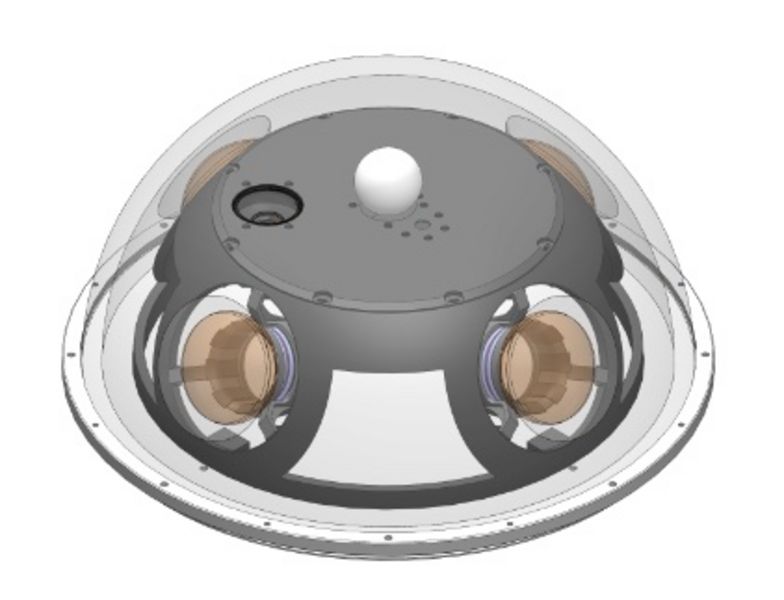
P-ONE's calibration scheme relies on two main systems: optical and acoustic calibration. The optical calibration is based on the emission of in-situ monitored sub-nanosecond high-power light pulses into the detector volume. The pulses are emitted uniformly with a diffusing PTFE sphere and monitored by the surrounding optical modules. A wide dynamic range ensures that close-by modules are not saturated and far modules can be reached, depending on the selected configuration. A photodiode and a SiPM will monitor the light flashes in situ. These principles are based on developments made for calibration light sources for the IceCube Upgrade. The pulser electronics will also be used for stand-alone flasher beacons integrated into all P-OMs. The 17" form factor of the instrument housings offered additional space to add PMTs in the module, allowing the P-CAL to serve as a hybrid module for calibration and detection. This avoids blind spots along the detector line while integrating dedicated calibration instruments.
The acoustic calibration will rely on acoustic transceivers distributed on the seafloor in reach of P-ONE-1. Their acoustic signals will be detected by piezo-based acoustic receivers, which are acoustically coupled to the glass hemispheres of each module. Additionally, the P-CAL will host a camera to monitor bioluminescence events and sedimentation effects on the instrument. Calibration setups have been constructed to develop, calibrate, and test the light emitters, in-situ photosensors, cameras, and acoustic receivers.
Data Acquisition & Time Synchronization
The signals of the 16 PMTs are read out by an analog-to-digital converter (ADC) with a sampling frequency of around 210 MHz and subsequently stored in a local ring buffer. The ADC readout allows us to collect full waveform data as input for event reconstruction and analysis. Event triggering is performed by tagging time-over-threshold (ToT) values with a PMT handle and time stamp and sending them to the trigger computer integrated in the mJB. After noise differentiation, signals of interest will be requested and sent to shore. The multi-PMT configuration allows the separation of bioluminescence events by local coincidence. The development of trigger algorithms is ongoing, and optimization will rely on in-situ data collected by P-ONE-1.
For this reason, untriggered data will be sent to shore for several months after deployment. PMT time-over-threshold rates will be permanently collected to monitor baseline changes due to seasonal, ocean, or climate variability. Proper event reconstruction requires sub-ns time synchronization within the instruments. To achieve this, a clock will be distributed to the individual modules in a star-like configuration. The modules will run with the same clock frequency and re-broad from the central hub inside the mJB via fiber to the mJB. Due to the different fiber lengths, a phase delay will be observed. Precise in-situ measurement of the phase differences allows sub-ns timing reconstruction and synchronization. The first prototype of the time synchronization and communication system, called BlackCat, is operational, and phase differences were measured and attributed in laboratory measurements.
The Deployment Concept
For the deployment of P-ONE-1, we pursue a bottom-up approach. In this process, the structure is packed into a deployment frame and lowered to the seabed. The line is then released by setting the float free. The deployment frame will be used for transportation, deployment, and potentially line recovery. At the beginning of the deployment, the frame is lowered to the seabed in a heavy lift operation. After this, a remotely operated vehicle (ROV) will inspect the integrated structure and perform the connection to the NEPTUNE infrastructure before the unfurling process. The ROV will release the float, and its buoyancy will lift the line while the ROV remains at the deployment frame to monitor the unfurling process.